Brand:ABB
Model:1VCF751021802D
Part No: 1VCF751021R802D
Describe: MAIN BOARD BOARD 6
Status: New/Used
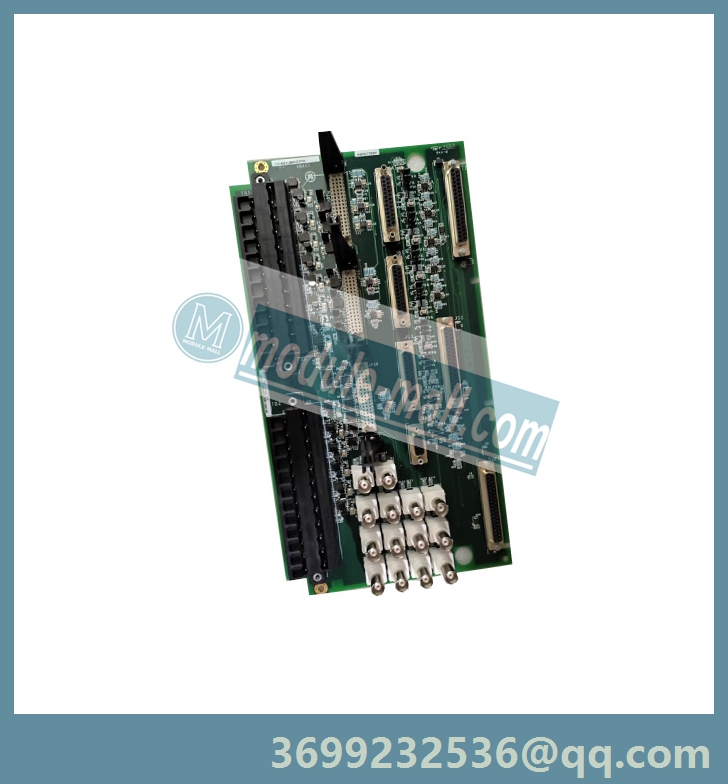
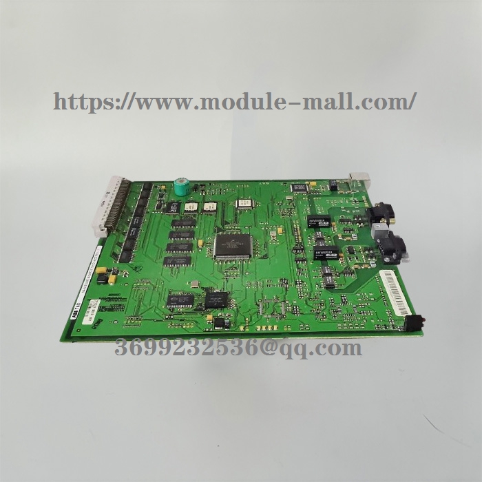
ABB MAIN BOARD BOARD 6 751021-802D
ABB 1VCF751021802D
ABB VCF751021802D MAIN BOARD BOARD 6 1VCF751021R802D
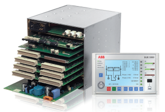
REF542plus host
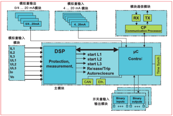
The REF542plus host is based on a real-time microprocessor architecture. The digital signal processor (DSP) performs protection functions, while the microcontroller (MC) performs control functions. Another processor on the optional communication module performs communication work with the power station automation system. This independent working method has high reliability. The block diagram of REF542plus is shown below. The motherboard is equipped with DSP and MC.
The open CAN interface, Ethernet interface for built-in web servers, and optocoupler input port for time synchronization are also located on the motherboard. The optional communication board is responsible for communication with the power station automation system.
overview
The switch input and output module is an interface that sends instructions to a primary device and obtains its status information. Analog input module obtains mutual inductance
The current and voltage signals of sensors or non-magnetic sensors.
The optional analog 0/4... 20 mA output module and analog 4... 20mA input module can convert relevant signals into 4... 20 mA or 0... 20 mA current signals.
REF542plus HMI
The HMI has a backlit liquid crystal display (LCD), 8 buttons, several LEDs, and an electronic key sensor. The application operation tool can select the display language among the available languages.
The left half of the LCD is used to display the single line diagram of the primary system controlled by REF542plus inside the switchgear. The right half of the LCD displays relevant information such as measurement and protection events using some abbreviations.
After maintaining a static state for 20 minutes, the background light of the LCD will automatically turn off.
HMI can fully implement on-site monitoring of switchgear. HMI allows operators to set protection parameters, operate equipment once, view measurement and event values, reset alarm signals, and change the working mode of this unit.
The HMI includes the following components:
Unit Ready
When this unit is in operation, this green LED lights up. When the power is interrupted or the unit is not working, this LED will turn off.
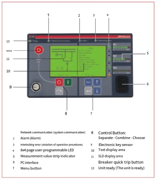
Network Communication
This LED is only meaningful if the REF542plus is configured with a communication module and has been set up. When this unit detects the presence of a communication module
At this time, this LED is in a green state. When there is no communication module or communication failure, this LED switches from green to red. When the unit is not equipped with communication function, this LED will turn off.
Alarm
When a user-defined alarm signal appears, this LED is in a red state. Application programming tools can define several alarm signals. The alarm signal can be a protective trip, a decrease in SF6 pressure inside the circuit breaker, and so on. When this LED lights up, it is necessary to first troubleshoot and confirm the alarm signal, otherwise the circuit breaker closing operation cannot be performed or a new setting program cannot be downloaded.
Interlocking Error
This LED is usually in a green state. When the user attempts to perform an operation that violates the interlock condition program that has been programmed, this LED immediately switches to red;
For example, when the circuit breaker is in the closed position, perform the closing operation of the grounding switch.
The electronic key sensor can be used to identify electronic keys. There are two different electronic keys available for selection. A key is used to change the parameters of the protection function. The other one is used to change the control mode. The sensor automatically detects the inserted key. For ease of identification, the two keys are marked with "Protect" and "Control" symbols respectively. When needed, a universal key can also be provided to enter these two modes. In addition, to improve security or for other special reasons, custom 8 characters can also be incorporated into the key. According to user needs, this requirement can be solved simply by applying a certain program.
Control buttons
These buttons can be used to operate the component once.
Menu Buttons
These buttons can be used to perform operations within the REF542plus menu.
8x4 page user programmable LED
8 programmable three color LEDs can be used as indicators. These indicator LEDs have a total of 4 pages. Application programming tools can define corresponding action conditions for LEDs.
PC interface
This is an optocoupler serial interface that connects REF542plus to a personal computer. Using a dedicated cable and programming tool can perform the following tasks:
Download the setup program into the device,
Upload the current setup program in the device,
Upload information from the fault recorder,
Upload other information (measurement values, switch input status, switch output status).
Measurement value bar indicator
Three programmable bar indicators can be used to visually check the load status of the switchgear. Three bar indicators are identified by M1, M2, and M3 respectively. Each indicator has a total of 12 LEDs: 10 green and 2 red. 10 green LEDs correspond to 0% to 100% of the nominal value of the measured object. Each LED corresponds to 10% of the nominal value. Two red LEDs each correspond to a 20% overload state. The measurement object using a bar indicator is selected by programming tools. The prompt for M1.. M3 can be set and displayed on the edge of the single line diagram.
Text display area
This is the text display area of the LCD. It can display menus, measurement values, event values, and relevant information within each level of menu.
SLD display area
This is the graphic display area of LCD. It can display the single line diagram of the switchgear. After each operation, the status display of a component can be updated in real-time: for example, after the circuit breaker is opened, its graphics can correspond to the actual status.
Quick release button for circuit breaker
Pressing this button at the same time as the regular disconnect button allows the circuit breaker to disconnect without being limited by the selected control mode. This function must be set up using programming tools to take effect on the device.
In addition, there are several command buttons on the HMI that can be customized by the user. These buttons can be operated within the HMI specific menu. When setting REF542plus, users need to define these buttons. Typical examples of button applications include starting the switch or other automation programs, activating the fault recorder, starting the uninstallation program, and so on.
By using user-defined command buttons, the automation capability of REF542plus can meet any application needs.
Other models: 1VCF750132807 , 1VCF750079801 , 1VCF750210802 , 1VCF701952803 ,1VCF750071801 ,1VCF750079801 ,1VCF750138803 ,1VCF750237801 ,1VCF751021802 , 1VCF751021-802d ,1VCF750126-801C,1VCF750126802 , 1VCR014629802 , 1VCF750168801 , 1VCF750170819