Brand: BENTLY NEVADA
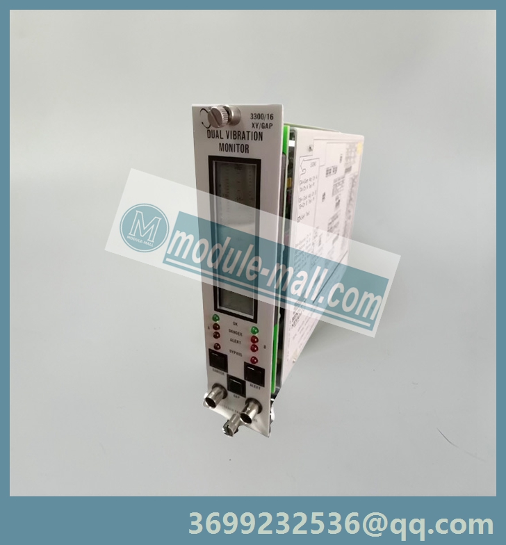
Model: 3300/16
Status: New/Used
Bently Nevada 3300/16 is a dual channel vibration monitoring board from the Bently Nevada brand 3300 series under Baker Hughes, designed specifically for industrial rotating machinery such as turbines, compressors, pumps, and fans. It adopts high-precision sensor interfaces and intelligent diagnostic algorithms, which can monitor vibration displacement, velocity, acceleration and other parameters in real time, support early fault warning and health assessment, and is the core component of "predictive maintenance" for industrial equipment.
BENTLY NEVADA 3300/16
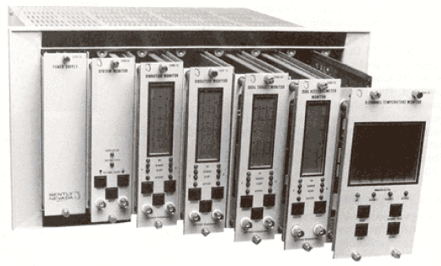
BENTLY NEVADA 3300/16 Dual Vibration Monitor
RADIAL VIBRATION - Radial vibration is defined as shaft dynamic motion in a directionperpendicular to the shaft centerline. The Dual Vibration Monitor displays values for twochannels (Channel A and B).
OK - When the Proximitor output voltage is within its upper/lower limits, the transducer is defined as OK. The OK detection circuit controls the channel OK LED and the monitor relay drive to the system Relay.OK RELAY - The OK Relay is located on the Power Input Module. Every channel in the rack must be OK or bypassed to energize the OK Relay.
TIMED OK/CHANNEL DEFEAT - Timed OK/Channel Defeat prevents faulty transducer wiring from causing false alarms. If the probe input signal level on a given channel is not within upper/lower OK limits, that channel OK LED goes off, the BYPASS LED goes on, the channel is disabled, and the OK Relay deenergizes. Once the channel input signal level is restored within the upper/lower OK limits for at least 30 seconds, the channel OK LED will start flashing at 1 Hertz (Hz) to indicate the OK state is restored, the BYPASS LED goes off, and monitoring is enabled. You must press the RESET switch on the front panel of the System Monitor to stop the OK LED from flashing (it will then remain on steadily). If the channel remains in the not OK state, set the Channel Bypass switch on the monitor circuit board to put the channel "out of service". You can then operate the monitor as a single-channel monitor, and the OK Relay will return to an OK state (energized). Without this feature, the OK Relay could not be reactivated. In the Timed OK/Channel Defeat and Channel Bypass modes, the recorder output is clamped to zero vibration value and the display is clamped to zero.
VIBRATION ALARM - Pressing the ALERT or DANGER switches on the front panel of the monitor displays the Alert (first-level alarm) or Danger (second-level alarm) vibration setpoints on the front panel meter. When the radial vibration signal level is equal to or exceeds preset Alert setpoints for the selected time delay, the ALERT LEDs come on and the appropriate Alert Alarm relay contacts are activated. When the radial vibration signal level exceeds preset Danger setpoints, the DANGER LEDs come on and the appropriate Danger alarm relay contacts are activated.
3300/16 Dual Vibration Monitor Operation Manual
GAP ALARM - Pressing the GAP and ALERT switches simultaneously displays the Gap Alert setpoints. When the gap level is equal to or outside the over and under setpoint window limits for 6 seconds, the ALERT LEDs come on and the appropriate Alert Alarm relay contacts are activated.
ALARMS RELAYS - Monitor alarms can operate in a latching or nonlatching mode. In the nonlatching mode, the alarm resets automatically when the alarm no longer exists. In the latching mode, you must reset the alarm condition manually by pressing the RESET switch on the front panel of the System Monitor (or by closing external Reset contacts). The alarm will not reset if the alarm condition still exists.
DANGER BYPASS - When you maintain machinery, you can set a Danger Bypass switch on the monitor circuit board behind the front panel to inhibit the Danger relay drive. This function causes the BYPASS LEDs to come on, but other front panel functions are not affected. You can enable this switch by installing a jumper on the circuit board in the monitor.
CHANNEL BYPASS - If a channel remains not OK, you can set the Channel Bypass switch on the monitor circuit board to put the channel "out of service".
ZERO POSITION - A reference gap value that you can set when the Gap Full Scale Range is in engineering units (mils or micrometers). You can then read gap on the meter scale relative to this zero position on the center of the gap meter scale. Selecting a Gap Full Scale Range in engineering units increases gap resolution on the display because only a selected area within the transducer's OK limits is displayed. BUFFERED OUTPUT - The coaxial cable connectors on the front panel of the monitor and the terminals on the Signal Input Relay Module provide buffered signals from the respective channel transducers. Use these connectors to attach external equipment to the monitor.
TRIP MULTIPLY - The Trip Multiply function multiplies setpoints by 2X or 3X in response to an external contact closure through terminals on the Power Input Module. The front panel meter and recorder outputs could saturate in this mode.
RECORDER OUTPUTS - The recorder output is proportional to the measured vibration signal over the monitor full-scale range. The output range is user selectable to be 0 to - 10Vdc, +1 to +5Vdc, or +4 to +20 mA.
The recorder clamping option, available when the +4 to +20 mA recorder output is selected, allows the user to choose the recorder output level used to annunciate a transducer not OK condition. With this option, the recorder output will clamp to either +2 mA or +4 mA (user selectable) when a transducer is not OK.
SELF-TEST - The monitor has three categories of self-test: Power-up, Cyclic, and User- invoked.
Power-up self-test is performed automatically each time the monitor power is turned on. A series of basic tests and transducer OK tests are performed.
Cyclic self-test is performed automatically during monitor operation. Errors encountered during cyclic tests disable the monitor and flash the error code on the LCD bargraph. If the error is intermittent, the monitor will resume operating, but the error codes will be stored for retrieval during a User-invoked self test. Stored error codes are indicated by the OK LEDs flashing at 5 Hz provided that the channel is OK.
User-invoked self-test performs the Power-up self test and lets you read and clear error codes stored during cyclic tests. Stored errors are annunciated by flashing the OK LEDs at 5 Hz and displaying the error codes on the front panel LCD bargraph.
Other models: 3300/01,3300/03 , 3300/05 , 3500/10 , 3300/12 , 3300/15 , 3300/16 , 3300/20, ,3300/25 , 3300/36,3300/40 , 3300/45 ,3300/48, 3300/50 , 3300/52, 3300/53, 3300/55 , 3300/65……
Email: [email protected]
BENTLY NEVADA 3300/16双振动监测仪
径向振动-径向振动被定义为轴在垂直于轴中心线的方向上的动态运动。双振动监测器显示两个通道(通道A和B)的值。
探头间隙电压-探头间隙测量为负直流电压,与接近探头表面和被监测表面之间的间隙距离成正比。按下gap开关,每个通道的探头间隙值将显示在前面板仪表上。
正常-当前置器输出电压在其上限/下限范围内时,传感器被定义为正常。正常检测电路控制通道正常LED和系统继电器的监测继电器驱动。OK继电器-OK继电器位于电源输入模块上。机架中的每个通道都必须正常或绕过,以给正常继电器通电。
定时正常/通道失效-定时正常/信道失效可防止传感器接线故障导致误报。如果给定通道上的探头输入信号电平不在OK上限/下限内,则该通道OK LED熄灭,旁通LED亮起,通道禁用,OK继电器断电。一旦通道输入信号电平恢复在OK上限/下限内至少30秒,通道OK LED将开始以1赫兹(Hz)的频率闪烁,表示OK状态已恢复,旁通LED熄灭,并启用监控。您必须按下系统监视器前面板上的RESET开关,以停止OK LED闪烁(然后它将保持稳定亮起)。如果通道仍处于非正常状态,请设置监视器电路板上的通道旁路开关,使通道“停止服务”。然后,您可以将监测器作为单通道监测器进行操作,OK继电器将返回OK状态(通电)。没有此功能,OK继电器无法重新激活。在定时OK/通道失效和通道旁路模式下,记录仪输出被箝位为零振动值,显示器被箝位至零。
振动警报-按下监视器前面板上的警报或危险开关,前面板仪表上会显示警报(一级警报)或危险(二级警报)振动设定点。当径向振动信号水平等于或超过所选时间延迟的预设警报设定点时,警报LED亮起,相应的警报继电器触点被激活。当径向振动信号水平超过预设的危险设定点时,危险LED亮起,相应的危险报警继电器触点被激活。
3300/16双振动监测仪操作手册
间隙报警-同时按下间隙和报警开关可显示间隙报警设定值。当间隙水平等于或超出上下限设定点窗口限制6秒时,ALERT LED亮起,相应的警报继电器触点被激活。
先出-警报和危险警报存在单独的先出电路。如果通道是自上次机架加电或重置以来机架中第一个进入报警的通道,则选择了“先出”选项的监视器会闪烁通道报警LED。按下系统监视器上的RESET开关,确认First Out。
警继电器-监测器报警可以在闭锁或非闭锁模式下运行。在非闭锁模式下,当报警不再存在时,报警会自动重置。在闭锁模式下,您必须通过按下系统监视器前面板上的重置开关(或关闭外部重置触点)手动重置报警状态。如果报警条件仍然存在,则报警不会重置。
危险旁路-维护机器时,可以在前面板后面的监视器电路板上设置一个危险旁路开关,以禁止危险继电器驱动。此功能会使旁通LED亮起,但其他前面板功能不受影响。您可以通过在显示器的电路板上安装跳线来启用此开关。
通道旁路-如果通道仍然不正常,您可以设置监视器电路板上的通道旁路开关,使通道“停止服务”。
零位置-当间隙满标度范围为工程单位(密耳或微米)时,您可以设置的参考间隙值。然后,您可以读取仪表刻度上相对于间隙仪表刻度中心零位的间隙。以工程单位选择间隙满标度范围可以提高显示器上的间隙分辨率,因为只显示传感器OK范围内的选定区域。缓冲输出-监测器前面板上的同轴电缆连接器和信号输入继电器模块上的端子提供来自各个通道传感器的缓冲信号。使用这些连接器将外部设备连接到显示器。
跳闸倍数-跳闸倍数功能将设定值乘以2X或3X,以响应通过电源输入模块上的端子的外部触点闭合。在此模式下,前面板仪表和记录器输出可能会饱和。
记录仪输出-记录仪输出与监测器满量程范围内的测量振动信号成正比。用户可选择输出范围为0至-10Vdc、+1至+5Vdc或+4至+20 mA。
当选择+4至+20 mA记录仪输出时,记录仪夹紧选项可用,允许用户选择用于通知传感器不正常状态的记录仪输出电平。使用此选项,当传感器不正常时,记录器输出将箝位到+2 mA或+4 mA(用户可选)。
自检-监视器有三类自检:通电、循环和用户调用。
每次打开监测器电源时,都会自动执行加电自检。执行一系列基本测试和传感器OK测试。
在监视器操作期间自动执行循环自检。循环测试期间遇到的错误会禁用监视器,并在LCD条形图上闪烁错误代码。如果错误是间歇性的,监视器将恢复运行,但错误代码将被存储,以便在用户调用的自检期间检索。如果通道正常,则存储的错误代码由以5 Hz闪烁的OK LED指示。
用户调用的自检执行加电自检,并允许您读取和清除循环测试期间存储的错误代码。通过以5 Hz的频率闪烁OK LED并在前面板LCD条形图上显示错误代码来通知存储的错误。
其他型号: 3300/01,3300/03 , 3300/05 , 3500/10 , 3300/12 , 3300/15 , 3300/16 , 3300/20, ,3300/25 , 3300/36,3300/40 , 3300/45 ,3300/48, 3300/50 , 3300/52, 3300/53, 3300/55 , 3300/65……
QQ:3699232536
购买咨询热线:18120742318