Brand:A-B
Model: 1771-OW
Status: New/Used
A-B 1771-OW
A-B 1771-OW
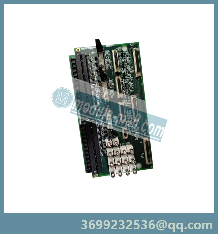
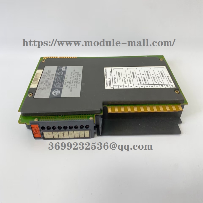
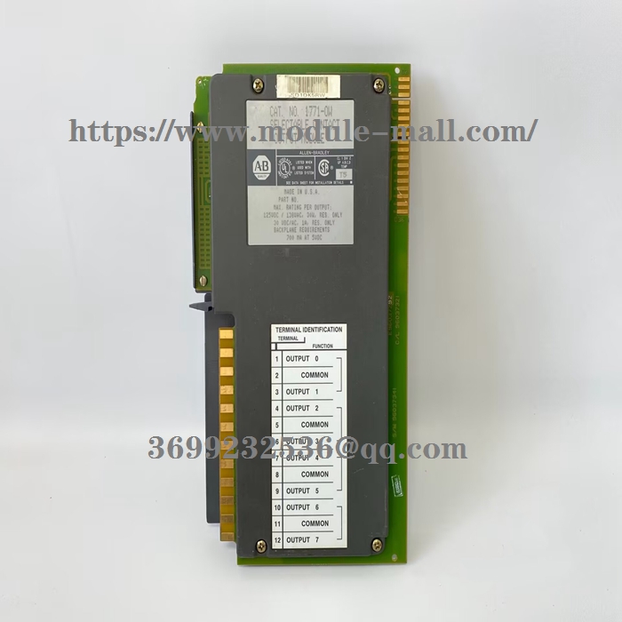
Selectable Contact Output ModuleCat. No. 1771–OW
Pre–installationConsiderations:These modules do not contain surge limiting circuitry. Use thesemodules for switching resistive loads only. They are notrecommended for inductive or capacitive loads.The outputs are arranged in 4 groups of 2, each group with its owncommon. Each output is electrically isolated from module logiccircuitry. The module can simultaneously switch all 8 outputs toseparate loads, each conducting a maximum load of 1.0Acontinuously, at rated power. Ac loads switched by the modulesshould have a power factor (PF) of 1.0.Maximum interconnect cable length for these modules is 1000 ft.(304.8 meters).
Power SupplyRequirements:The controller or I/O chassis power supply, connected through thebackplane of the I/O chassis, powers the logic circuitry of the contactoutput modules. This supply also provides the necessary power toenergize the coils of the module relays. The maximum current drawnfrom this supply when all coils are energized is 700mA.
Installing Your Module:In this section we tell you how to initially handle your module, keyyour I/O chassis, set the relay output jumpers, install your moduleand make your wiring connections.
Initial Handling Procedures
ATTENTION: Remove power from the 1771 I/Ochassis backplane and wiring arm before removing orinstalling an I/O module.
• Failure to remove power from the backplane or wiring arm could cause module damage, degradation ofperformance, or injury.
• Failure to remove power from the backplane couldcause injury or equipment damage due to possibleunexpected operation.
The contact output module contains components which can bedamaged by electrostatic discharge. The module is shipped in anelectrostatic shielded bag for protection. Follow the handlingprocedures outlined below to guard against damage to your module.
• Touch a grounded object to discharge yourself before handlingthe module.
• Do not touch the backplane connector or connector pins.
• If you configure or replace internal components, do not touchother circuit components inside the module. If available, use astatic–safe work station.
• When not in use, keep the module in its static–free shield bag
Keying the I/O Chassis
Use the plastic keying bands, shipped with each I/O chassis, to keyyour I/O slots to accept only this type of module. Place the keyingbands on the chassis backplane between:
• 6 and 8
• 16 and 18
Slots on the rear edge of the circuit board are matched to these slotsto allow insertion of this type of module. You can key any connectorin an I/O chassis to receive this module except for the leftmostconnector reserved for adapter or processor modules.
Setting the Relay Output Jumpers
When the output image table bit at the address corresponding to anyoutput is energized (set to 1), the corresponding relay contact isclosed or opened, respective to the jumper setting.
All outputs are individually selectable for either normally–open ornormally–closed operation. They are pre–set for normally–openoperation at the factory. To reset any jumper, proceed as follows:
1. Remove the 4 screws from the side cover and separate the circuitboard from the 2 covers.
2. Move the jumper to the desired position (see below). Jumpers areidentified by jumper number and use (N.O. or N.C.).
3. Reinstall the circuit board in the module and replace the cover.

Inserting the Module Into the Chassis
1. Position the module so that the circuit board on the rear of themodule lines up with the top and bottom card guides in thechassis.
2. Slide the module into the chassis.
3. Press firmly to seat the module in the chassis backplaneconnector.
4. Swing the module locking latch down into place over the frontedge of the module.
Connecting Wiring to the Module
You make connections to the module through the field wiring armcat. no. 1771–WD. The arm pivots on the I/O chassis to connect withterminals on the front of the module and acts as a terminal strip. Thewiring arm allows the module to be removed from the chassiswithout disconnecting wiring.
1. Make certain all power is removed from the module beforemaking wiring connections.
2. Swing the wiring arm up into position on the front of the module.The locking tab on the module will secure it into place.
3. Make your connections to the field wiring arm as shown below.(Use the label on the front of the wiring arm to identify yourwiring.)
ATTENTION: The field wiring arm terminalidentification number is not the same as the number ofthe bit which controls that output.


ATTENTION: Do not attempt to increase loadcurrent or wattage capability beyond the rating byconnecting two or more outputs in parallel. Theslightest variation in output relay switching time maycause one set of contacts to switch the total loadcurrent.
Interpreting the StatusIndicators :The module has 8 status indicators on the module front plate. Theserepresent the control status of the output relays. Each indicator is litwhen its corresponding relay is energized.

Specifications

Other models:1771-NT2 ,1771-OA ,1771-OAD ,1771-OB ,1771-OBN ,1771-OD ,1771-OD16 ,1771-ODD ,1771-OFE1 ,1771-OFE