Brand: SST
Model:5136-PFB-PCI
Part No: 5136-PFB-PCI
Describe:Interface card
Status: New/Used
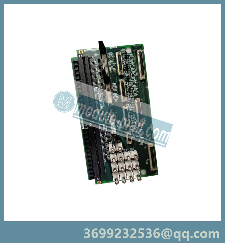
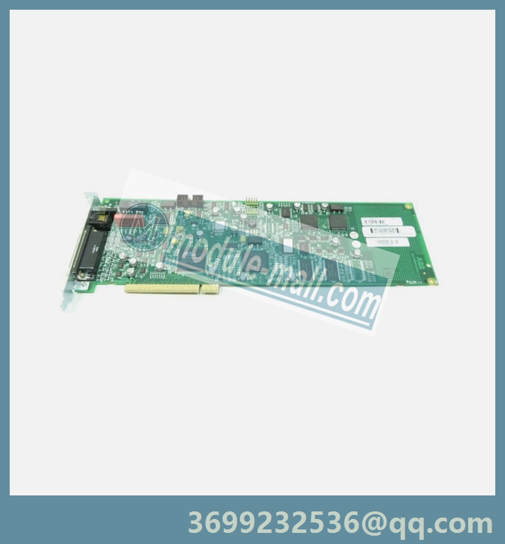
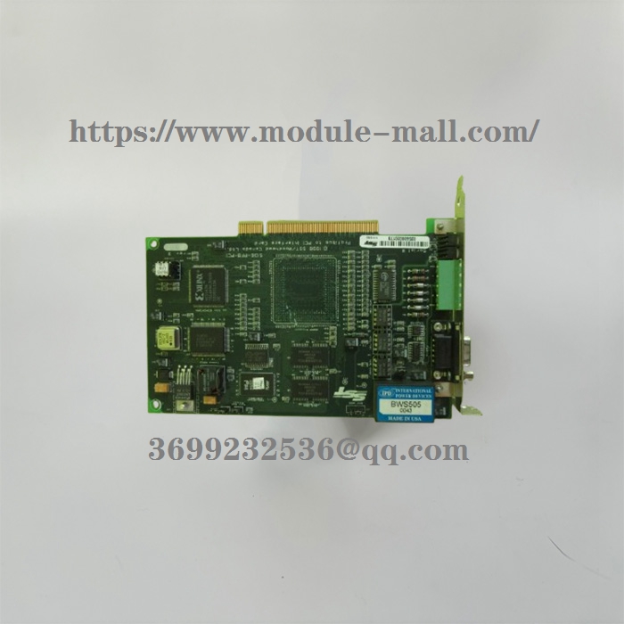
SST-5136-PFB-PCI Interface card
SST-5136-PFB-PCI
Card Overview
The SST-PBF3-PCI is the next Generation Profibus PCI card. When possible, backward compatibility is maintained with the legacy 5136-PFB-PCI, but the new SST-PFB3-PCI is not a drop in replacement for the existing 5136-PFB-PCI card.
The 5136-PFB-ISAand the SST-PFB3-PCI card can:
• Act as a DP slave
• Act as a DP master
• Send and receive FDL (layer 2) messages
• Support Master Class 2
• Support simultaneous operation in all of the above modes
• Support the standard Profibus baud rates of 9.6K, 19.2K, 93.75K, 187.5K, 500K, 750K, 1.5M, 3M, 6M and 12M baud.
Note: The SST-PFB3-PCI does not support FMS messaging.
While control of the legacy 5136-PFB-PCI card (for example, interrupts and reset) was handled by writing to the PCI configuration space, this is no longer the case with the new SST-PFB3-PCI.
The SST-PFB3-PCI card is controlled through a separately mapped PCI memory area. This memory area is also used to access new features, like the ability to read the LED status. The PCI configuration space of the new design does not normally need to be written to by the host application; it is normally only used by the host system drivers to determine where card resources have been allocated in the host system.
5136-PFB-PCI Configuration Space
The 5136-PFB-PCI card has two PCI devices:
• Function 0: Primary PCI to PCI bridge that is not used by the card for any ProfiBus-related functions
• Function 1: Secondary PCI to i960 local ram bridge (ATU) that is the primary shared RAM interface to the card.
5136-PFB-PCI Configuration Space Table

Loading the 5136-PFB-PCI
1. Follow these steps to load the 5136-PFB-PCI:
2. Read the Primary Inbound ATU Base Address at PCI register 4, function1, and save this value for later use.
3. Read the ATU Interrupt Line Register from register 0Fh of function1 and save this value for later use. The interrupt line value is the least significant byte of this register.
4. Reset the i960 by using bit 5 of the Extended Bridge Control Register (10h of function 0). Wait for i960 to come up.
5. Restore the saved values from steps 1 and 2 to the primary inbound ATU Base Address register and ATU Interrupt Line Register, respectively.
6. Enable the 5136-PFB-PCI card memory space by setting bit 1 (02h) of the Primary ATU Command Register (function1, register 1). Wait for the boot code to start by monitoring the byte location at base address + 1FFFFFh for the value BAh.
7. Load the card module (pcipfrofi.ss1) to memory starting at base address +1000h.
8. Write a 01 to base address +1FFFFFh to tell the boot code to run the firmware.
9. Wait for the firmware start up to complete by monitoring the base address +1FFFFF for the value 5Ah. The firmware copyright message and version string will be present at base address 1FFF00Hh.
10. Clear the byte at base address +1FFFFFHh to allow the firmware to continue.11. Wait for the pfbCommand Register (base address + 8000h) to be set to E0h.
12. The implementation of PNP BIOS is defined by the PCI SIG. Please refer to the PCI Local Bus Specification Rev 2.1 and PCI BIOS Specification Rev 2.1. The latter document will define how to access the PCI configuration space of the 5136-PFB-PCI card.
5136-PFB-PCI Technical Data